Page 84 - Piper PA-22 Tri-Pacer Interactive Digital Parts Catalog
P. 84

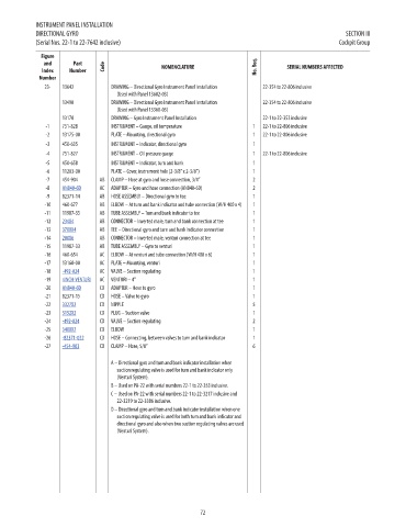
INSTRUMENT PANEL INSTALLATION
            DIRECTIONAL GYRO                                                                             SECTION III
            (Serial Nos. 22-1 to 22-7642 inclusive)                                                    Cockpit Group

             Figure
              and      Part
              Index   Number    Code              NOMENCLATURE                No. Req.  SERIAL NUMBERS AFFECTED                   PRICE
             Number
              23-   13642         DRAWING – Directional Gyro Instrument Panel Installation    22-354 to 22-806 inclusive          NM!
                                    (Used with Panel 13602-03)
                    13490         DRAWING – Directional Gyro Instrument Panel Installation    22-354 to 22-806 inclusive          NM!
                                    (Used with Panel 13360-03)
                    13170         DRAWING – Gyro Instrument Panel Installation  22-1 to 22-353 inclusive                          NM!
               -1   751-828       INSTRUMENT – Gauge, oil temperature        1  22-1 to 22-806 inclusive                          NM!
               -2   13175-00      PLATE – Mounting, directional gyro         1  22-1 to 22-806 inclusive                          NM!
               -3   450-635       INSTRUMENT – Indicator, directional gyro   1                                                    NM!
               -4   751-827       INSTRUMENT – Oil pressure gauge            1  22-1 to 22-806 inclusive                          NM!
               -5   450-658       INSTRUMENT – Indicator, turn and bank      1                                                    NM!
               -6   11203-00      PLATE – Cover, instrument hole (2-3/8” x 2-3/8”)  1                                             NM!
               -7   454-904    AB  CLAMP – Hose at gyro and hose connection, 3/4”  2                                              NM!
               -8   AN840-6D   AC  ADAPTER – Gyro and hose connection (AN840-6D)  2                                               11.96
               -9   82371-14   AB  HOSE ASSEMBLY – Directional gyro to tee   1                                                    NM!
              -10   460-677    AB  ELBOW – At turn and bank indicator and tube connection (W/H 400 x 4)  1                        NM!
              -11   11987-35   AB  TUBE ASSEMBLY – Turn and bank indicator to tee  1                                              NM!
              -12   234X4      AB  CONNECTOR – Inverted male, turn and bank connection at tee  1                                  7.9
              -13   3700X4     AB  TEE – Directional gyro and turn and bank indicator connection  1                               1
              -14   200X6      AB  CONNECTOR – Inverted male, venturi connection at tee  1                                        2.76
              -15   11987-33   AB  TUBE ASSEMBLY – Gyro to venturi           1                                                    NM!
              -16   460-654    AC  ELBOW – At venturi and tube connection (W/H 400 x 6)  1                                        NM!
              -17   13160-00   AC  PLATE – Mounting, venturi                 1                                                    NM!
              -18   -492-024   AC  VALVE – Suction regulating                1                                                    24.95
              -19   4INCH-VENTURI  AC  VENTURI – 4”                          1                                                    78.82
              -20   AN840-6D   CD  ADAPTER – Hose to gyro                    1                                                    11.96
              -21   82371-15   CD  HOSE – Valve to gyro                      1                                                    NM!
              -22   3327X2     CD  NIPPLE                                    5                                                    2.64
              -23   3152X2     CD  PLUG – Suction valve                      1                                                    1.42
              -24   -492-024   CD  VALVE – Suction regulating                2                                                    24.95
              -25   3400X2     CD  ELBOW                                     1                                                    2.93
              -26   -82371-022  CD  HOSE – Connecting, between valves to turn and bank indicator  1                               28.73
              -27   -454-903   CD  CLAMP – Hose, 5/8”                        6                                                    2.43


                                  A – Directional gyro and turn and bank indicator installation when
                                    suction regulating valve is used for turn and bank indicator only
                                    (Venturi System).
                                  B – Used on PA-22 with serial numbers 22-1 to 22-353 inclusive.
                                  C – Used on PA-22 with serial numbers 22-1 to 22-3217 inclusive and
                                    22-3219 to 22-3386 inclusive.
                                  D – Directional gyro and turn and bank indicator installation when one
                                    suction regulating valve is used for both turn and bank indicator and
                                    directional gyro and also when two suction regulating valves are used
                                    (Venturi System).


                                                             72
   79   80   81   82   83   84   85   86   87   88   89